


To use the Hudson Eagle safely and effectively, carefully read through the links to the left. The Hudson Eagle is simple to use, but precautions MUST be followed to avoid injuries.
Authorized Use by Trained Personnel Only!
Operator MUST read and be familiar with all instructions and safety procedures, prior to any operations or service.
Failure to follow all warnings and instructions could result in severe injury, or even death, of those on or around this device.
Operator MUST "Call Out" a warning prior to any operations.
Always visually inspect system for damage or wear, and make sure working area is completely clear of all obstructions and personnel prior to any operation. DO NOT operate system until these conditions are determined safe!
All operation of system control valves MUST be done SLOWLY and SMOOTHLY.
Prior to permitting any personnel access to the work area, all motion MUST have stopped, both safety stop latches MUST be verified by the operator to be engaged, and ALL air lines MUST be disconnected to prevent any unauthorized operation.
DO NOT modify or alter this system or any of the components without prior written approval from the manufacturer. Use only manufacturer approved attachments or parts on this system.
-
Check all hydraulic lines for damage or leaks, and replace as necessary before any usage.
-
Check all visible lifting straps for excessive wear or damage and replace as necessary before any usage.
-
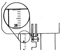
Check drive chain for proper adjustment (see Fig.1), and inspect for wear or damage. Replace as necessary before any usage.
-
Check air system oiler level, add approved air motor oil to the air line oiler reservoir as necessary before any usage.
-
Inspect all Safety Latch components for excessive wear or damage, and make sure they work freely. Do not operate system without these functioning properly!
-
Inspect all fasteners for tightness. Verify that all retainer clips are in place. Tighten or replace as necessary before any use.
-
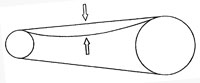
Verify the elevation alignment between both carriers "under load" (see Fig. 2). Do Not operate the system if the alignment exceeds tolerance of a 1 1/2" variation between both carrier elevations. Remove strap cover to adjust center link turnbuckle as necessary, before any usage. (See carrier height adjustment procedures)
Fig. 1
Physically clear the entire working area of any obstructions and all personnel.
Attach air line to air up system.
Raise the mold to {40} inches as indicated on the primary carrier (control end) alignment scales (see Fig. 1).
With the carriers being free (not down on the safety latches) note the measured variation between both carriers. This measured difference is the adjustment needed to be made at the center link turnbuckle.
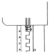
Fig. 2
Insert carrier safety stop pins supplied into the I-Beam in the holes just below each carrier (See Fig. 2) and secure it with the spring pins supplied with safety stop pins.
Raise the mold slightly, then the reset the safety latches to the" lowering the mold position".
Slowly lower the mold until both carriers are firmly resting upon the inserted safety stop pins. These safety stop pins must always be in place while working underneath the mold.
The carriers and mold will now be 12 inches out of parallel (not level). This temporary disalignment takes tension out of the center link strap and turnbuckle and allows for ease in adjustment.
Remove the second center strap cover closest to the secondary end of the system. This will expose the center link adjustment turnbuckle for adjustment.
Adjust the turnbuckle the same amount as the difference between both carrier elevations noted earlier (usually tightened/shortened).
Move everyone back from under the mold and physically clear the area.
Raise the mold back up to 40 inches or until the mold is free, not down on any of the safety stops.
Re-check the carrier elevation. If it is within the allowable tolerance you may proceed to the next step, otherwise repeat the above process until the variation is within the specified tolerance.
Raise the mold until the safety stops automatically re-engage. Slowly lower the mold unto the auto safety latches.
Once at safe rest, reinstall the center link strap covers.
Remove the safety stop pins. Resume normal safe operation.
- Physically clear the entire working area of all personnel and any obstructions.
- Attach air line.
- Engage the elevation control valve, slowly and smoothly.
- Open air gate valve slowly but adequately to operate system, raising the system vertically.
- As the system reaches the position desired, ease the air control valve off to a smooth stop.
A noticeable clacking sound at both ends of the system indicates a properly functioning, auto-engaging safety latch catch system. This function MUST be functioning properly at all times during the elevation procedure, without exception.
- Once the desired elevation is reached, slowly shut the air gate valve off.
- Slowly release the control valve. Once stopped, slowly and smoothly reverse the elevation control valve to lower the system onto the auto-setting safety latch catches.
- The operator MUST now make sure both stops are loaded and that the lifting system is at rest.
- Physically clear the entire working area of all personnel and any obstructions.
- Attach air line.
- Engage the elevation control valve, slowly and smoothly.
- Open air gate valve slowly but adequately to operate system, raising the system vertically.
- Raise the system vertically just enough to take pressure off the safety latches.
- Once stopped, shut off air gate valve and manually release both safety latches.
- Engage the elevation control handle slowly and smoothly to lower the system vertically.
- Once the desired location is reached release tghe control valve slowly and smoothly.
- If the system is lowered completely it will come to rest on the mainstops. However, if the system is to be stopped above this level you must re-engage the safety latches.
- To reset the safety latches engage the elevation control handle slowly, open air gate valve slowly but adequately to operate the system. Raise the system just enough to engage the latches on both ends. A loud clack will be heard as each latch re-engages.
- Slowly shut off air gate valve, and slowly release the elevation control valve.
- Now slowly and smoothly reverse the elevation control valve to lower the system firmly onto the safety latch stops.
- The operator MUST now make sure both stops are loaded and that the lifting system is safely at rest.
- Physically clear the entire working area of all personnel and any obstructions.
- Attach air line.
- Verify that system is ay correct height for desired rotation.
- Slowly and smoothly engage the rotation control valve.
- Open air gate valve slowly but adequately to operate system, while rotating the system in the direction desired.
- As the system reaches the desired position, ease the air control valve off to a smooth stop.
ONLY when the system is safely at rest may personnel (re)enter the working area.
Clean rotation drive chain weekly.
Replace rotation drive chain every three years.
Replace lifting straps every two years.
Replace hydraulic fluid, filter, and pickup strainer once a year.
Every three months remove covers and inspect all three lifting straps and related hardware for wear or damage and replace as necessary.